| Design Standard: |
ANSI B16.34;API608 |
| Wall Thickness Standard: |
ANSI B16.34;EN12516-3 |
| Thread Standard: |
ANSI B1.20.1;BS21;DIN2999/259;ISO228-1;ISO7;JIS B0203 |
| Socket Welding Standard: |
ASME B16.11 |
| Butt Weld End Standard: |
ASME B16.25;ISO1127;EN12627 |
| Flange End Standard: |
ASME B16.5 CLASS 150/300;EN1092-1;HG20592 GB/T9113 PN10-PN40;JIS B2238 10K/20K |
| Test Standard: |
API 598;EN 12266 |
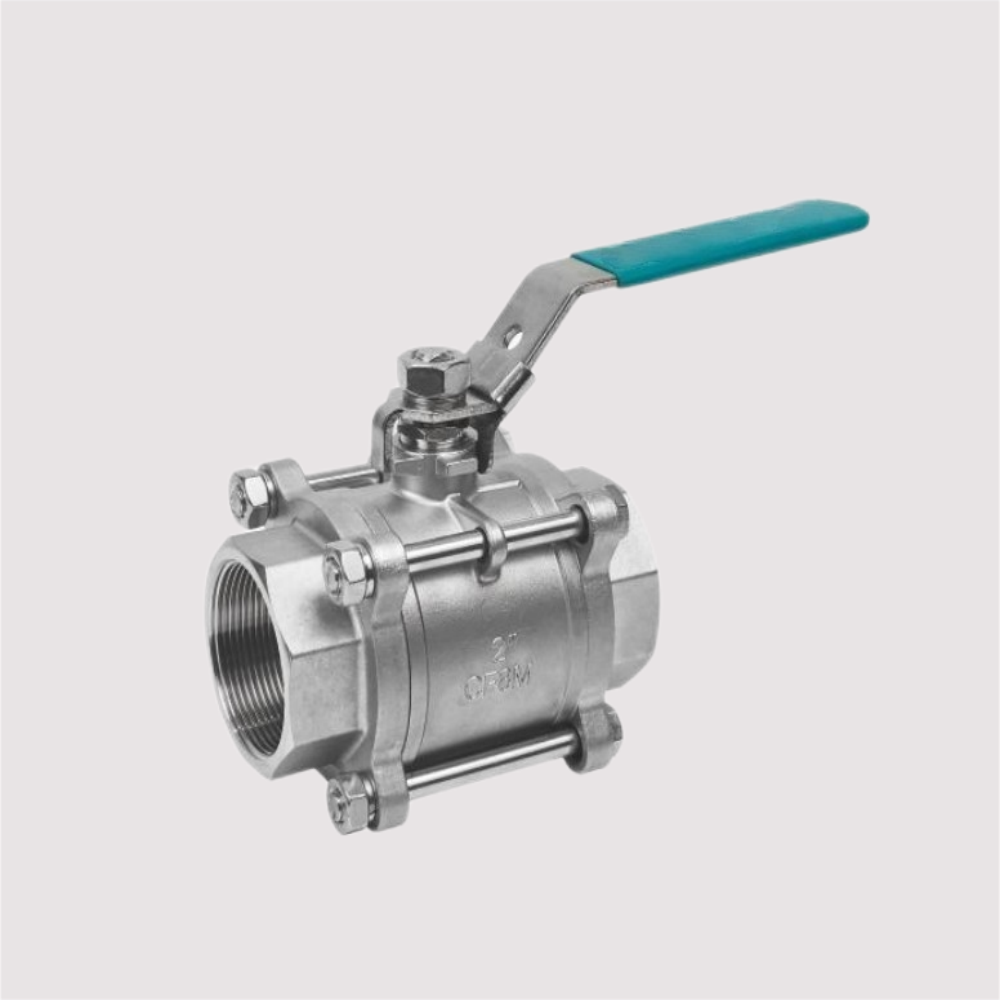
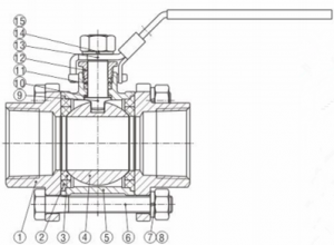
| NO. | Name |
Material |
| 1 | Bonnet |
A351 CF8/A351 CF8M/A216 WCB |
| 2 | Seal line |
PTFE/RPTFE |
| 3 | Seat |
PTFE/RPTFE/CPTFE/PPL/PEEK |
| 4 | Ball |
SUS304/SUS316 |
| 5 | Body |
A351 CF8/A351 CF8M/A216 WCB |
| 6 | Bolt |
SUS304 |
| 7 | Gasket |
SUS304 |
| 8 | Nut |
SUS304 |
| 9 | Stem |
SUS304/SUS316 |
| 10 | Anti-wear gasket |
PTFE/RPTFE |
| 11 | V-type packing |
PTFE/RPTFE |
| 12 | Gland |
SUS304 |
| 13 | Handle |
SUS304 |
| 14 | Gasket |
SUS304 |
| 15 | Stem nut |
SUS304 |
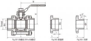
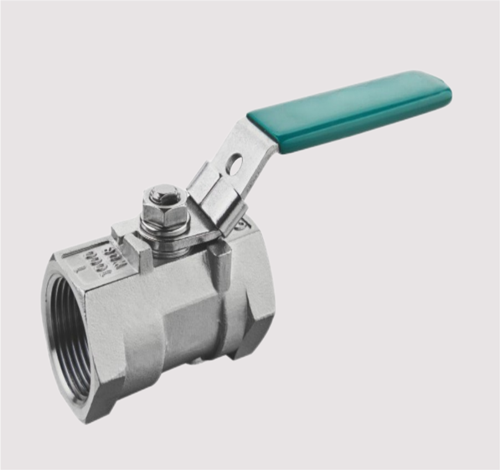
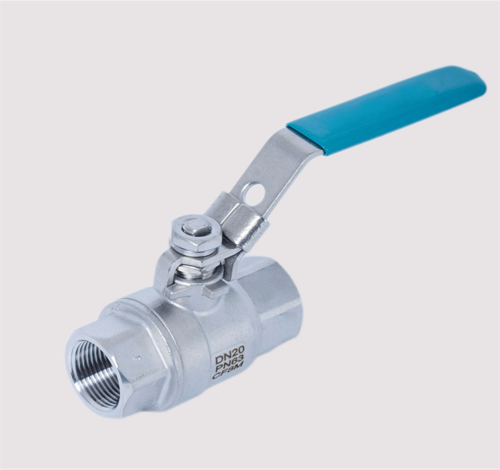
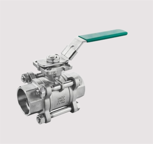
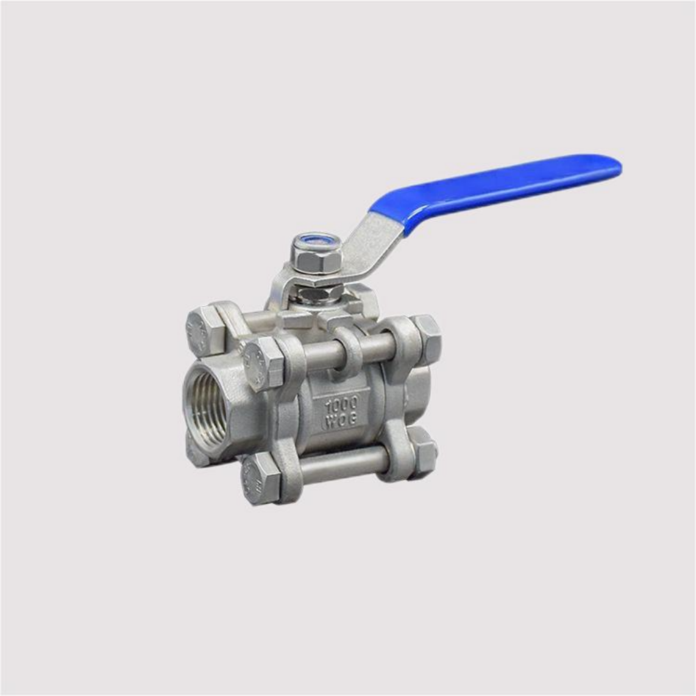
| Female Thread/Male Thread/Socket Weld/Butt Weld Ball Valve(Fig.301/301a 302/303 1000psi ) | |||||||||||
| Size | d | L | D | t | F | H | W | ||||
| a type | b type | c type | d type |
ISO1127 EN12627 SMS3008 |
|||||||
| 1/2" | DN15 | 15 | 75 | 62 | 75 | 75 | 22.2 | 9.5 | 21.7 | 52 | 110 |
| 3/4" | DN20 | 20 | 80 | 68 | 80 | 80 | 27.6 | 12.5 | 27.2 | 63 | 120 |
| 1" | DN25 | 25 | 90 | 81 | 90 | 90 | 34.3 | 12.5 | 34 | 67 | 130 |
| 1 1/4" | DN32 | 32 | 110 | 96 | 110 | 110 | 43.1 | 12.5 | 42.7 | 80 | 140 |
| 1 1/2" | DN40 | 38 | 120 | 106 | 120 | 120 | 49.2 | 12.5 | 48.6 | 93 | 175 |
| 2" | DN50 | 49 | 140 | 128 | 140 | 140 | 61.7 | 16 | 60.5 | 110 | 175 |
| 2 1/2" | DN65 | 64 | 185 | / | 185 | 185 | 74.4 | 16 | 76.3 | 117 | 220 |
| 3" | DN80 | 76 | 205 | / | 205 | 205 | 90.3 | 16 | 88.9 | 134 | 270 |
| 4" | DN100 | 100 | 240 | / | 240 | 240 | 115.7 | 19 | 114.3 | 157 | 310 |
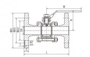
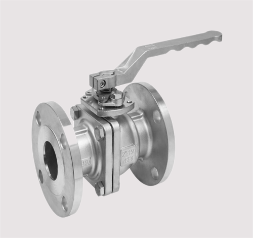
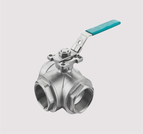
| GB/DIN Flange Ball Valve (GB/DIN PN16/PN40) | ||||||||||
| Size | DN | L | D | D1 | D2 | C | T | N-Φd | N | W |
| 1/2" | 15 | 130 | 95 | 65 | 45 | 16 | 2 | 4-Φ14 | 52 | 110 |
| 3/4" | 20 | 150 | 105 | 75 | 58 | 18 | 2 | 4-Φ14 | 63 | 120 |
| 1" | 25 | 160 | 115 | 85 | 68 | 18 | 2 | 4-Φ14 | 67 | 130 |
| 1 1/4" | 32 | 180 | 140 | 100 | 78 | 18 | 2 | 4-Φ18 | 80 | 140 |
| 1 1/2" | 40 | 200 | 150 | 110 | 88 | 18 | 3 | 4-Φ18 | 93 | 175 |
| 2" | 50 | 230 | 165 | 125 | 102 | 20 | 3 | 4-Φ18 | 110 | 175 |
| 2 1/2" | 65 | 290 | 185 | 145 | 122 | 18 | 3 | 4-Φ18 | 123 | 220 |
| 3" | 80 | 310 | 200 | 160 | 138 | 20 | 3 | 8-Φ18 | 135 | 240 |
| 4" | 100 | 350 | 220 | 180 | 158 | 20 | 3 | 8-Φ18 | 160 | 300 |
Startup
(1)In the closed position, the ball is pressed against the valve seat by the mechanical pressure of the valve stem.
(2)When the hand wheel is turned counterclockwise, the valve stem moves in the opposite direction, and the angular plane at the bottom makes the ball
disengage from the valve seat.
(3)The valve stem continues to lift and interacts with the guide pin in the helical groove of the valve stem, causing the ball to start rotating without friction.
(4)Until it reaches the fully open position, the valve stem is raised to the limit position, and the ball rotates to the fully open position.
Shutdown
(1)When closing, turn the handwheel clockwise, the valve stem starts to drop and the ball leaves the valve seat to start rotating.
(2)Continue to rotate the handwheel, and the valve stem is acted by the guide pin embedded in the spiral groove on it, so that the valve stem and the ball
rotate 90° at the same time.
(3)When it is about to close, the ball has rotated 90° without contact with the valve seat.
(4)In the last few turns of the handwheel, the angular plane at the bottom of the valve stem mechanically wedges against the ball to press it tightly against
the valve seat to achieve a complete seal.
Helping you with our 10 years experiences of valve products industry